
How to Talk to a Cobot
https://www.isel-us.com/cartesian-gantry-robotsFor the purposes of these notes we will consider a project interfacing a COBOT to a Cartesian Gantry machine. In most cases the COBOT is loading and unloading parts while the Gantry or router is performing an operation on the part - e.g. inspection, drilling, spot welding, glueing.... The same principals can be applied to any combination of robot or cobot with a Cartesian Gantry or XY stage or milling machine or any other configuration machine. At the minimum, both the COBOT and the Gantry need 1 free DIGITAL INPUT and 1 free DIGITAL OUTPUT
One bite at a time.
That is pretty much how you put together a CIM cell as well. Imagine designing a complicated machine, such as a https://www.isel-us.com/cartesian-gantry-robotsCIM cell (cobot + Cartesian Gantry machine) or a space shuttle, putting it all together and then turning it on – with the expectation that it will work…Whenever a large project is undertaken, whether it is a long computer program or complicated machine, the only way to realistically design and develop it is ONE STEP AT A TIME. Each component, each section should be designed, built and tested individually before assembling the entire system.
Preparing a design for the proposed Cobot cell should be the first step. A flow chart outlining the process and the steps should be developed. As a suggested first step in the process, the Cobot cell can be thought of in the following sections:
Now that the project is divided into more manageable sections, the first tendency is to have 4 people work on the 4 parts independently. This is a good idea BUT BE CAREFUL. Each of the 4 sections should be designed and developed WITH the idea that they are going to be integrated. There is no point in having each section work but then not be able to put them together. As one simple example:
The cobot will usually be handling a simple part.
Make sure the AUTOMATION program is not going to make a part that the cobot will not be able to pick up and remove from the fixture. YOU MIGHT NEED DUAL END EFFECTORS!
Do not be drawn in by the concept of only learning what is necessary to get the job done. You never know what will be necessary down the road or what opportunities are waiting on the next page of the manual. The main emphasis in this document will be in developing the interface between the Cobot and Cartesian Gantry machine. The concepts described here are universally used in operations requiring inputs, outputs, and digital communications and manufacturing in general. The partner machine does not necessarily have to be a CNC type machine. It could just as easily be a belt driven Cartesian Gantry that might be used for a high speed inspection or glue dispensing application.
This outline will focus exclusively on the interface communications between the Cobot and the Cartesian Gantry machine. This communication will be handled with digital signals. You can think of this as raising and lowering different colored flags to signal a YES or NO. As long as the 2 people that are communicating understand what each colored flag represents, they can easily communicate. The following is a simplified outline of how to handle the communication between the Cobot and the CARTESIAN GANTRY machine:
Implementation beats oration. – Aesop
There is a program language available on the Isel Controllers (PAL for stepper controllers and PRONC for servo controllers). This program is used for automation type applications that require outputs to be turned on and off and inputs to be monitored. PRONC also allows the controller to execute GCODE programs during the course of a program.
The general flowchart for the program is shown above. The details now have to be implemented. This is a pretty straightforward exercise from the CARTESIAN GANTRY machine side.
PRONC, the Isel control language, can be used to interface the CARTESIAN GANTRY machine to the Cobot. The Cobot is expected to load and unload parts into an automatic vice that is also controlled by the Cobot. Once the blank part is loaded, the Cobot can signal the Isel controller that the part is ready to be machined. Once the Isel controller completes the machining operation, it signals the Cobot that the operation is complete. The Cobot can then unload the completed part and reload a fresh blank and the process can be repeated as often as necessary. Note that the 2 flowcharts for the Cobot and the CARTESIAN GANTRY machine CANNOT be synchronized.
Each machine checks for signals from the other machine BUT the 2 machines operate independently!
AT THE MINIMUM, we only need one INPUT and one OUTPUT ON EACH MACHINE to implement the flowchart.
The inputs and outputs are used for “hand shaking” or signaling between the Isel controller and the Cobot. The sample program shows a proposed communications system between the Cobot and the CARTESIAN GANTRY. The program outline is as follows:
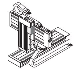
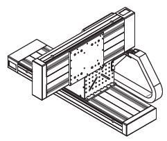
Customized configurations of robot devices can easily be assembled from either ball screw actuators or for high speed applications, belt drive actuators.
 |
 |
| Example of Cartesian Gantry Robot with dual axis drives on the base axis. This configuration is sometimes referred to as an "H" Frame | Example of Cartesian Gantry Robot with flatbed table and single axis drive down the center |
-
Breaking Up Big Problems into Manageable Pieces
One bite at a time.
That is pretty much how you put together a CIM cell as well. Imagine designing a complicated machine, such as a https://www.isel-us.com/cartesian-gantry-robotsCIM cell (cobot + Cartesian Gantry machine) or a space shuttle, putting it all together and then turning it on – with the expectation that it will work…Whenever a large project is undertaken, whether it is a long computer program or complicated machine, the only way to realistically design and develop it is ONE STEP AT A TIME. Each component, each section should be designed, built and tested individually before assembling the entire system.
-
The Suggested Pieces
Preparing a design for the proposed Cobot cell should be the first step. A flow chart outlining the process and the steps should be developed. As a suggested first step in the process, the Cobot cell can be thought of in the following sections:
- GCODE or AUTOMATION or INSPECTION program to process the part
- Cobot program to load the part
- Cobot program to unload the finished part
- Interface program to have the Cobot and Cartesian Gantry machine work together
-
Watch Out for the GOTCHAS
Now that the project is divided into more manageable sections, the first tendency is to have 4 people work on the 4 parts independently. This is a good idea BUT BE CAREFUL. Each of the 4 sections should be designed and developed WITH the idea that they are going to be integrated. There is no point in having each section work but then not be able to put them together. As one simple example:
The cobot will usually be handling a simple part.
Make sure the AUTOMATION program is not going to make a part that the cobot will not be able to pick up and remove from the fixture. YOU MIGHT NEED DUAL END EFFECTORS!
-
It Is Legal to Use These Skills Elsewhere
Do not be drawn in by the concept of only learning what is necessary to get the job done. You never know what will be necessary down the road or what opportunities are waiting on the next page of the manual. The main emphasis in this document will be in developing the interface between the Cobot and Cartesian Gantry machine. The concepts described here are universally used in operations requiring inputs, outputs, and digital communications and manufacturing in general. The partner machine does not necessarily have to be a CNC type machine. It could just as easily be a belt driven Cartesian Gantry that might be used for a high speed inspection or glue dispensing application.
-
Interfacing the Cobot to the Cartesian Gantry Machine
This outline will focus exclusively on the interface communications between the Cobot and the Cartesian Gantry machine. This communication will be handled with digital signals. You can think of this as raising and lowering different colored flags to signal a YES or NO. As long as the 2 people that are communicating understand what each colored flag represents, they can easily communicate. The following is a simplified outline of how to handle the communication between the Cobot and the CARTESIAN GANTRY machine:
 |
 |
| Schematic of how to talk to a Cobot (click on image to enlarge) |
Flowchart of how to talk to a Cobot (click on image to enlarge) |
-
How to Implement the Flowchart
Implementation beats oration. – Aesop
There is a program language available on the Isel Controllers (PAL for stepper controllers and PRONC for servo controllers). This program is used for automation type applications that require outputs to be turned on and off and inputs to be monitored. PRONC also allows the controller to execute GCODE programs during the course of a program.
The general flowchart for the program is shown above. The details now have to be implemented. This is a pretty straightforward exercise from the CARTESIAN GANTRY machine side.
PRONC, the Isel control language, can be used to interface the CARTESIAN GANTRY machine to the Cobot. The Cobot is expected to load and unload parts into an automatic vice that is also controlled by the Cobot. Once the blank part is loaded, the Cobot can signal the Isel controller that the part is ready to be machined. Once the Isel controller completes the machining operation, it signals the Cobot that the operation is complete. The Cobot can then unload the completed part and reload a fresh blank and the process can be repeated as often as necessary. Note that the 2 flowcharts for the Cobot and the CARTESIAN GANTRY machine CANNOT be synchronized.
Each machine checks for signals from the other machine BUT the 2 machines operate independently!
AT THE MINIMUM, we only need one INPUT and one OUTPUT ON EACH MACHINE to implement the flowchart.
. |
| (click on image to enlarge) |
The inputs and outputs are used for “hand shaking” or signaling between the Isel controller and the Cobot. The sample program shows a proposed communications system between the Cobot and the CARTESIAN GANTRY. The program outline is as follows:
- The Cobot sends a HIGH signal when it has completed its task of loading a part.
- Once the Cartesian Gantry receives the Cobot signal on the Techno Input, the Cartesian Gantry sends a HIGH signal to the Cobot to indicate that it is completing the machining task.
- Once the Cartesian Gantry has completed the machining task, it moves back to a clearance location and once there, it changes the HIGH signal to a LOW signal to indicate to the Cobot that the machining is complete and the CARTESIAN GANTRY machine is ready for the next part.
- The Cobot now turns its output to LOW to indicate that it will unload the finished part and load a new blank part.
- The Cobot can now unload the finished part and reload a new blank part and the process can be repeated as often as desired.
 |
 |
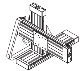 |
| XYZ Cartesian Robot | XY Cartesian Robot | XYZ Cartesian Robot |
Customized configurations of robot devices can easily be assembled from either ball screw actuators or for high speed applications, belt drive actuators.