
LFS-12-3 Linear Rails and Bearings


The LFS-12-3 linear rail can be combined with several different carriage options to handle applications where a single wider rails is needed due to cantilevered loads.
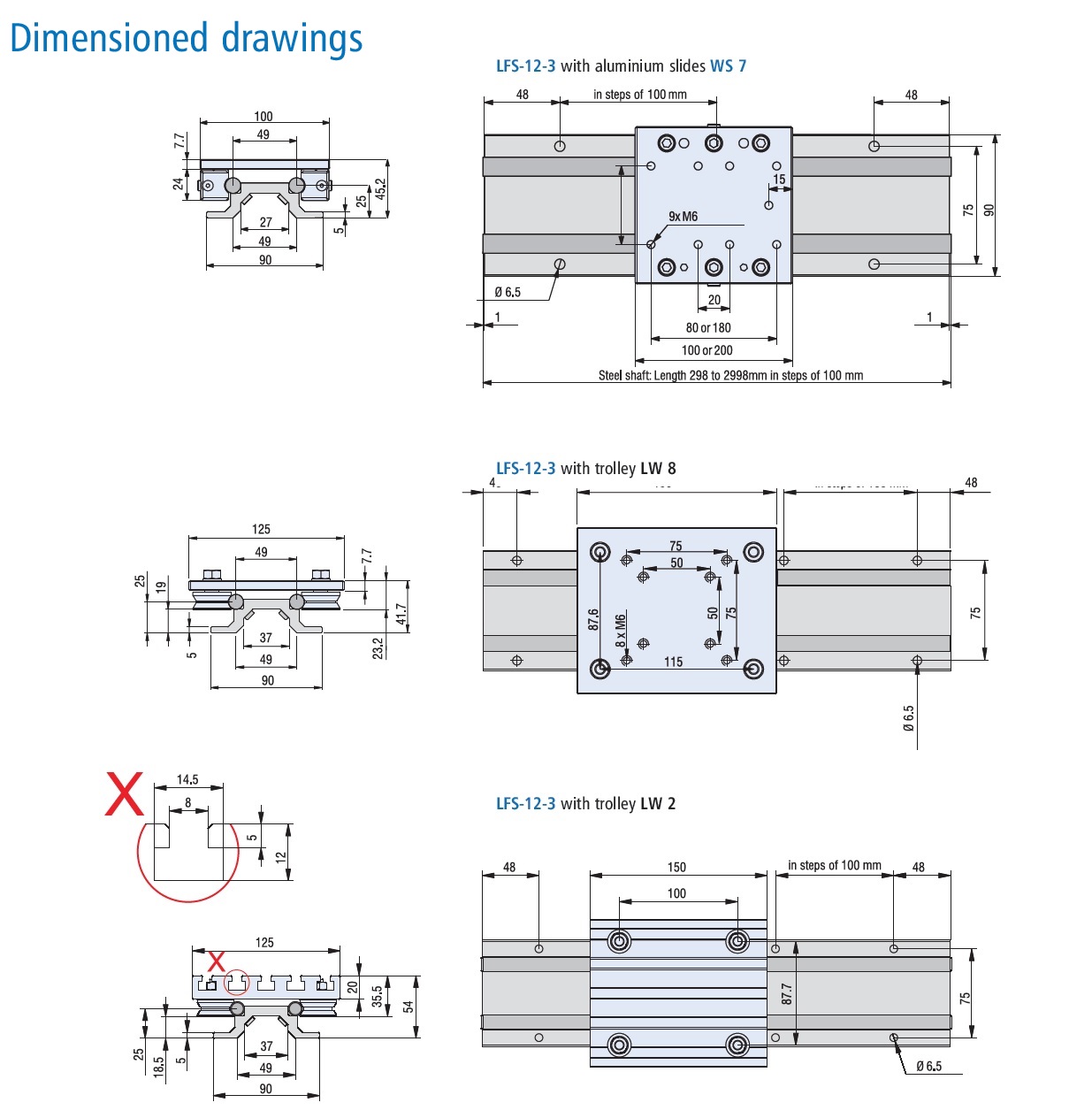
Two 12mm diameter steel rails are supported uniformly through the length of travel by a clear anodized 90 mm wide aluminum support profile
Guide rails consist of two precision GERMAN ground Ø12 mm h6 steel shafts with M5 threaded holes spaced 100 mm apart.
The shafts are hardened to RC62 +2 for durability against heavy loads and virtually no wear
The double rail and support profile is sold as a complete assembly in lengths from 400 mm to 3000 mm
Longer lengths with staggered rails are available on special order. 3m sections can be joined to make virtually any required length rail.
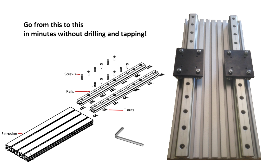
The support profile has mounting holes 75 mm apart at 100 mm intervals along the system length. This allows for QUICK MOUNT to our Heavy-Duty Extrusion Plates or other mounting surfaces.
MADE IN GERMANY!
Click here for bearing and roller carriage options and specifications.
View and Download LFS 12-3 Catalog Pages
Get A Quote!
Two 12mm diameter steel rails are supported uniformly through the length of travel by a clear anodized 90 mm wide aluminum support profile
Guide rails consist of two precision GERMAN ground Ø12 mm h6 steel shafts with M5 threaded holes spaced 100 mm apart.
The shafts are hardened to RC62 +2 for durability against heavy loads and virtually no wear
The double rail and support profile is sold as a complete assembly in lengths from 400 mm to 3000 mm
Longer lengths with staggered rails are available on special order. 3m sections can be joined to make virtually any required length rail.
The support profile has mounting holes 75 mm apart at 100 mm intervals along the system length. This allows for QUICK MOUNT to our Heavy-Duty Extrusion Plates or other mounting surfaces.
MADE IN GERMANY!
Click here for bearing and roller carriage options and specifications.
View and Download LFS 12-3 Catalog Pages
Get A Quote!
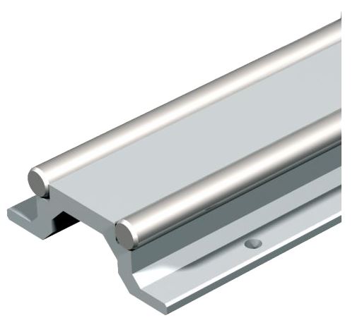 |
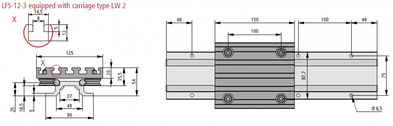
LFS 12-3 Wide Rail
Can be QUICK MOUNTED on PT 25 extrusionsHas 4 linear bering choices Wide body makes it resistant to cantilevered or off center loads 2x12mm ground hardened steel rails Available in 100mm increments from 200 to 3000mm Can be provided with overlapping butt joints to make longer rails Part # 235300 XXXX (XXXX length in mm) MADE IN GERMANY |
 |
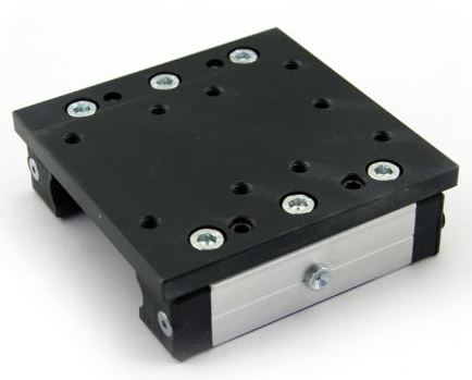
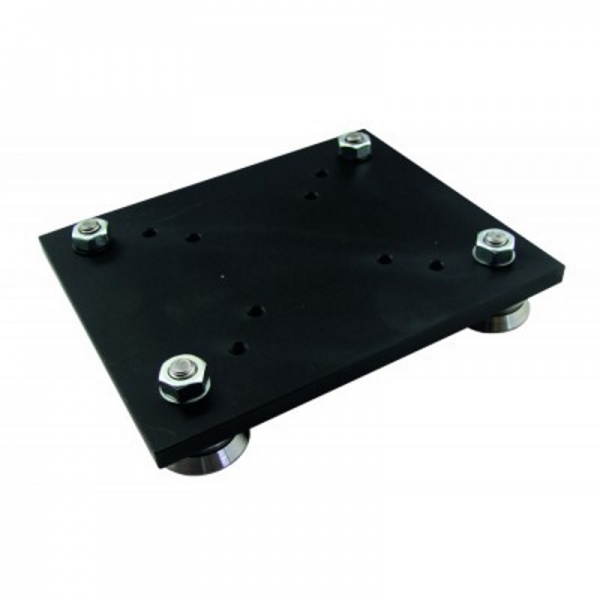
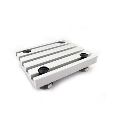
LW 2 T Slot V Roller Bearing
V rolllers are sealed and are ideal for dusty environmentsT Slot surface makes it easy to mount parts and service payloads - just loosen the T nuts, service the part and retighten the T nuts! Part # 223005 Specifications Dimensioned drawing Solid Model |
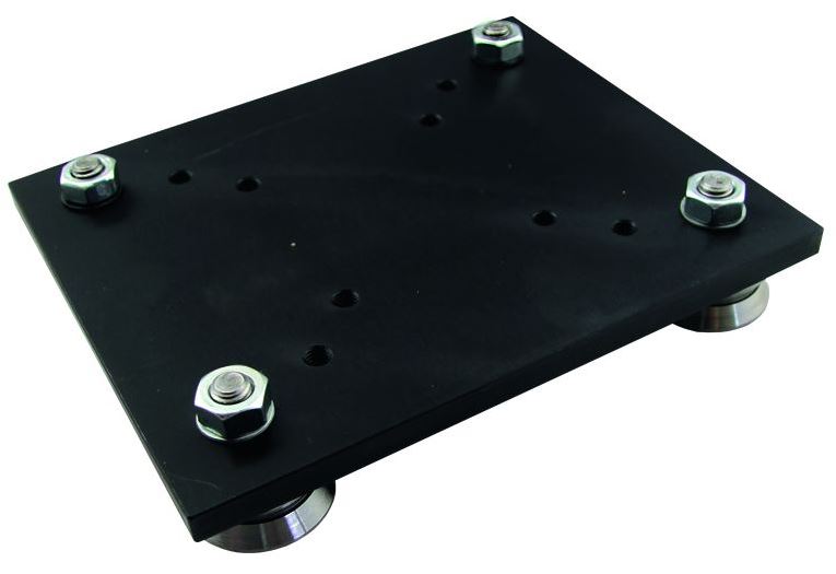 |
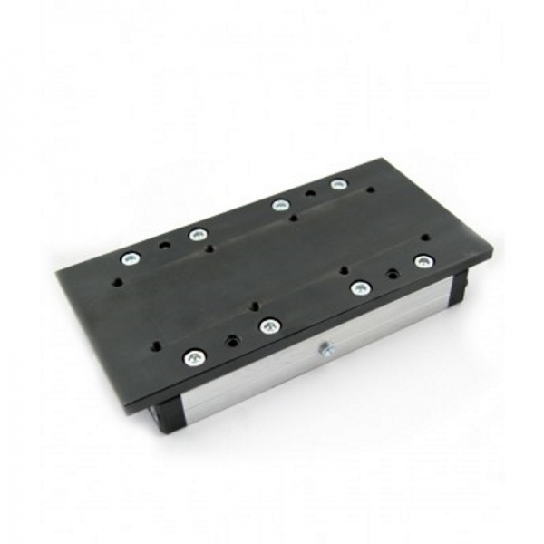
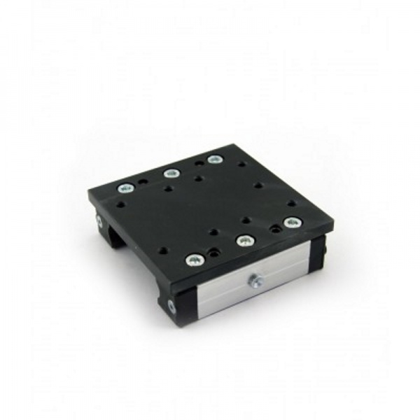
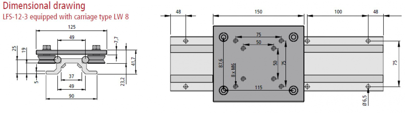
LW 8 V Roller Bearing with Ground Steel Plate
V rolllers are sealed and are ideal for dusty environmentsGround steel bearing plate is durable and stiff against cantilevered loads Part # 223013 Specifications Dimensioned drawing Solid Model |
 |
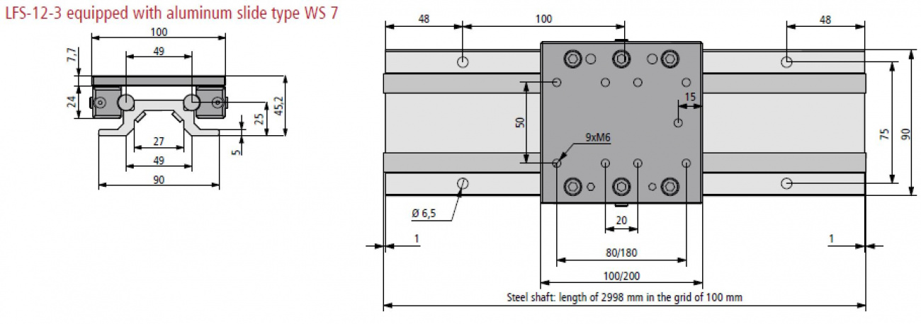
WS 7/70 Short Recirculating Linear Bearing
Load is distributed among the many ball bearingsRolling action of steel balls reduces wear for very long life Can be used in any orientation Preadjusted for zero play and long life Part # 223107 0070 Specifications Dimensioned drawing Solid Model |
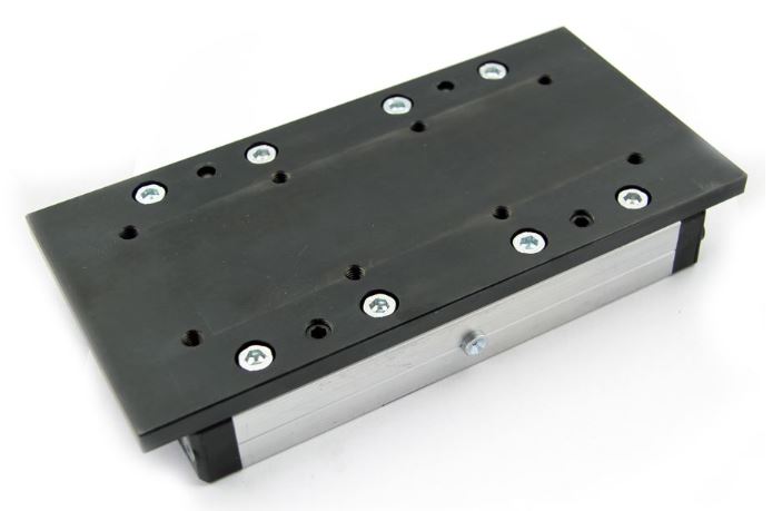 |
WS 7 Long Recirculating Linear Bearing
Load is distributed among the many ball bearingsRolling action of steel balls reduces wear for very long life Can be used in any orientation Preadjusted for zero play and long life Part # 223107 Specifications Dimensioned drawing Solid Model |
Configure Your Part
Select Options then Click “Add to Quote”
Part Number:
|
| Add To Quote |
Extra Images
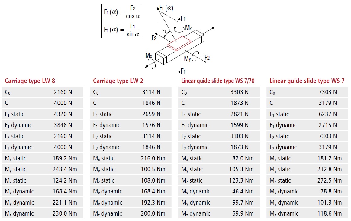
| LFS 12-3 | ||||||||||
| Shaft slides WS 7 | Shaft slides WS 7/70 | Trolley LW 2 | Trolley LW 8 | |||||||
| C0 | 7303 N | C0 | 3303 N | C0 | 3114 N | C0 | 2160 N | |||
| C | 3179 N | C | 1873 N | C | 1846 N | C | 4000 N | |||
| F1 static | 6237 N | F1 static | 2821 N | F1 static | 2659 N | F1 static | 4320 N | |||
| F1 dynamic | 2715 N | F1 dynamic | 1599 N | F1 dynamic | 1576 N | F1 dynamic | 3846 N | |||
| F2 static | 7303 N | F2 static | 3303 N | F2 static | 3114 N | F2 static | 2160 N | |||
| F2 dynamic | 3179 N | F2 dynamic | 1873 N | F2 dynamic | 1846 N | F2 dynamic | 4000 N | |||
| Mx static | 181.2 Nm | Mx static | 82.0 Nm | Mx static | 216.0 Nm | Mx static | 189.2 Nm | |||
| My static | 232.8 Nm | My static | 105.3 Nm | My static | 100.5 Nm | My static | 248.4 Nm | |||
| Mz static | 272.5 Nm | Mz static | 123.3 Nm | Mz static | 108.0 Nm | Mz static | 124.2 Nm | |||
| Mx dynamic | 78.8 Nm | Mx dynamic | 46.4 Nm | Mx dynamic | 168.4 Nm | Mx dynamic | 168.4 Nm | |||
| My dynamic | 101.3 Nm | My dynamic | 59.7 Nm | My dynamic | 192.3 Nm | My dynamic | 221.1 Nm | |||
| Mz dynamic | 118.6 Nm | Mz dynamic | 69.9 Nm | Mz dynamic | 200.0 Nm | Mz dynamic | 230.0 Nm | |||
